| Suitable for safety functions |
Yes |
| Voltage type |
DC |
| Rated control supply voltage at DC |
24 V |
| Type of switching output of the OSSD |
PNP |
| Type of electric connection |
Screw connection |
| Galvanic de-coupling |
Yes |
| Power up time |
9 s typical |
| Voltage level, max |
-29…29V @ TxD+, TxD |
| Short-circuit current |
-60…60 mA @ TxD |
| Size of light spot |
27 mm @ 5.0 m scanning range |
| Power consumption, max |
55 W (with maximum output load) |
| Operating current, max |
2.3 A (with maximum output load) |
| Part number |
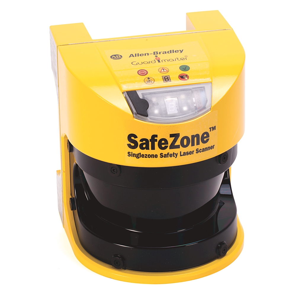
Safezone multizone safety laser scanner head |
| Cable length for power supply tolerance ±10% |
50 m maximum for cable cross-section 1 mm² |
| Cable length for power supply tolerance ±5% |
60 m maximum for cable cross-section 1 mm² |
| Cable length for power supply tolerance ±1% |
70 m maximum for cable cross-section 1 mm² |
| Warning field |
Approx. 20 m typical (For objects with 20% reflectivity.) |
| Resolution |
30, 40, 50, 70, 150 mm |
| Protective safety field of the sensor head |
5.00 m maximum @ 70 mm resolution, 120 ms response time, with 5.0 m scanning range |
| Measurement error |
Systematic error: ±5 mm (Measured data error output up to 5.0 m, 1.8% reflectivity) |
| Number of protected semiconductor outputs |
2 |
| With configurable message output |
Yes |
| With restart blockage |
Yes |
| With alert field output |
Yes |
| Laser protection class |
Class 1 |
| Distance measuring range |
49 m |
| Distance from mirror axis of rotation (zero point on the X and Y axis) to the rear of the device |
93 mm |
| Distance between centre of the scan plane and the bottom edge of the housing |
63 mm |
| Test frequency |
120 ms |
| Switching time of the OSSDs from red to green |
120 ms |
| Divergence of the collimated beam |
2.5 m rad |
| Pulse duration, max |
3.1 ns |
| Output power, max |
562 μW |
| Reflectivity |
0.018 |
| Restart (after configurable) |
2 s |
| Cable cross-section of the connecting cable |
0.25 mm² |
| Angular resolution |
0.5 ° |
| System connector |
ESD protected |
| Protective safety field supplement generally necessary |
100 mm maximum |
| Supplement for retroreflectors in scan plane at a distance of less than 1 m to the protective safety field boundary |
200 mm maximum |
| Sender |
Pulsed laser diode |
| Evenness of the scan field |
±70 mm maximum @ 5.0 m |
| Load capacity |
2.2 μF maximum @ 50 Ohm |
| Characteristic impedance of the connecting cable |
80 Ω…115 Ω (100 Ω typical) |
| Number of multiple samplings |
2…16 (configurable via SCD) |
| Time offset on switching the OSSDs between OSSD2 and OSSD1 |
1.3 ms typical…2 ms maximum |
| Switch OFF delay |
0.7 ms typical…2 ms maximum |
| Terminating resistance |
115 Ω…125 Ω (120 Ω typical) |
| Differential input threshold at the receiver |
±0.2V min. (between RxD+ and RxD-) |
| PFD – probability of failure on demand |
4.46E-3 (minimum requirement = 1E-2) |
| Type of connecting cable |
Twisted pairs with copper braid screen |
| Differential output voltage at the sender |
±2…±5V (between TxD+ and TxD-), with 50 ~ load |
| Switch on current |
2 A maximum (The load currents for the input capacitors are not taken into account) |
| Switching sequence |
Depending on load inductance (without switching and without simultaneous monitoring) |
| Load inductance |
2.2 H maximum (the maximum rated load inductance is higher with lower switching sequence) |
| Permissible residual ripple |
±5% maximum (The absolute voltage level must not drop below the specified minimum voltage) |
| Power up delay |
1.4 ms typical…2 ms maximum (Application diagnostic outputs warning field, contamination of the front screen/error, reset necessary) |
| Current limiting |
600…920 mA (after 5 ms at 25 °C) (Application diagnostic outputs warning field, contamination of the front screen/error, reset necessary) |
| Supply voltage (SELV) |
16.8…28.8V (24V typical), The voltage supply must be capable of buffering brief mains voltage failures of 20 ms as specified in EN 60 204. |
| Test pulse width |
230 μs typical…300 μs maximum (when active, the outputs are tested cyclically (brief LOW). When selecting the downstream controllers, make sure that the test pulses do not result in deactivation) |
| Permissible cable resistance |
2.5 Ohm maximum (make sure to limit the individual line core resistance to the downstream controller to this value to ensure that a short-circuit between the outputs is safely detected (also note EN 60 204-1)) |
%2002_4C.jpg)
There are no reviews yet.